Bala Hydropower Station — a key project under Sichuan's hydropower development plan for the 14th Five-Year Plan
(Contributed by Sichuan Qingyuan Engineering Consulting Co., Ltd.)
一: Project Overview
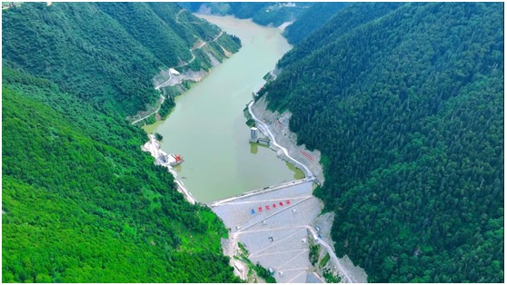
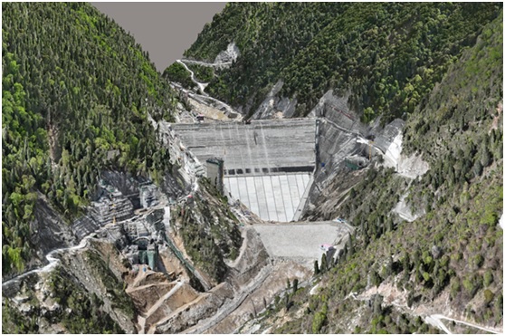
The Bala Hydropower Station is located in Maerkang City, Ngawa Tibetan and Qiang Autonomous Prefecture, Sichuan Province. It is the second cascade (counting from upstream to downstream) among the “3 reservoirs and 28 cascades” planned along the main stem of the Dadu River. The project is situated downstream of the Xi’erqia “leading” reservoir hydropower station and upstream of the Dawei Hydropower Station.Classified as a Grade II large (2) project, Bala employs a hybrid development scheme. A 140-meter-high concrete-faced rockfill dam (CFRD) is constructed approximately 2.2 km downstream of the Sejiang Suspension Bridge, where the river valley is relatively narrow and the terrain is geologically intact.A pressurized diversion tunnel, approximately 6.7 km long, runs along the right bank to convey water to an underground powerhouse situated within the mountain on the right bank of the Jiaomuzu River, about 3.9 km upstream of the Ribu Suspension Bridge. Water is discharged back into the river via a 1.7-km-long tailrace tunnel, exiting the canyon to complete the overall engineering layout of the Bala Hydropower Station.
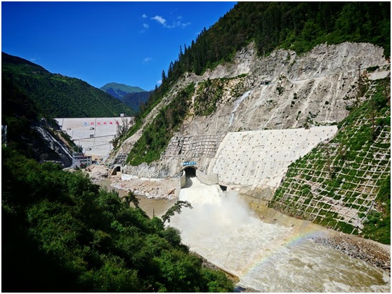
The river-blocking dam is a concrete-faced rockfill dam (CFRD).On the left bank, the spillway structures consist of an open-type overflow tunnel and a flood discharge and reservoir emptying tunnel.On the right bank, a shore tower intake and a diversion tunnel are arranged.
Key design parameters are as follows:
- Normal pool level: 2,920.00 m
- Total reservoir capacity: 124.5 million m³ (1.245 × 10⁸ m³)
- Dam crest elevation: 2,925.00 m
- Dam axis length: 286.50 m
- Maximum dam height: 140.00 m
Spillway Tunnel (Open-Type)
- Type: Open inlet with free-surface flow and ski-jump energy dissipation at an oblique cut outlet
- Total length: 1,324 m
- WES weir crest elevation at inlet: 2,903.00 m
- Control gate height: 43.5 m
- Tunnel cross-section: D-shaped, with a maximum excavation span of 20 m
Flood Discharge and Reservoir Emptying Tunnel
- Layout: Combination of a pressurized long conduit followed by an unpressurized tunnel
- Total length: 834.00 m
- Inlet invert elevation: 2,845.00 m
- Pressurized section:
- Length: 270.00 m
- Circular cross-section with internal diameter D = 7.4 m
- Unpressurized section:
- Length: 493.00 m
- D-shaped cross-section, internal width: 7.0 m
- Vertical wall height: 7.94–10.8 m
- Outlet energy dissipation: Dual-surface differential ski-jump structure
This configuration ensures safe flood discharge, reservoir drawdown capability, and effective energy dissipation in the steep canyon environment.
The ecological powerhouse is located downstream of the main dam. The ecological generating unit draws water at the junction between Construction Adit No. 1 and the main pressurized diversion tunnel.The penstock for the ecological unit has a main pipe internal diameter of 3.3 m, and the installed capacity is 26 MW.
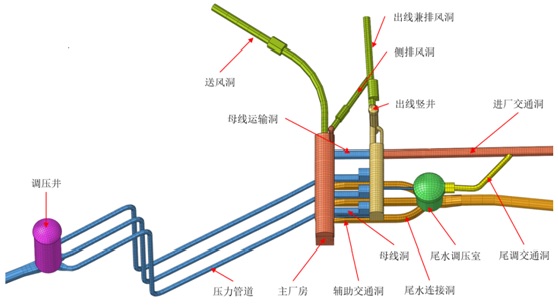
The diversion (water conveyance) system comprises the following main structures:
- Powerhouse intake
- Diversion tunnel
- Upstream surge chamber
- Penstocks (pressure pipelines)
Intake Structure
- Type: Shore tower intake
Diversion Tunnel
- Total length: 6,731.65 m
- Invert elevation at inlet: 2,895.00 m
- Invert elevation at upstream surge chamber: 2,870.00 m
- Longitudinal slope: i = 3.749‰ (downward toward the surge chamber)
- Cross-section: Circular, with a maximum excavation diameter of 14.1 m
Upstream Surge Chamber
- Type: Cylindrical impedance surge chamber
- Height: 90.5 m
- Excavation diameter of shaft: 32.4–33.4 m
- Excavation diameter of dome: 37.0 m
- Lined internal diameter: 30.0 m
Penstocks (Pressure Pipelines)
- Arrangement: One pipe per unit, parallel layout
- Internal diameter: 5.6 m
- Length: Approximately 155 m
Tailrace Surge Chamber
- Type: Cylindrical impedance surge chamber
- Excavation diameter of dome: 51.6 m
- Excavation diameter of shaft: 33.8 m
- Lined internal diameter: 30.80–31.80 m
- Height: 44.47 m
This configuration ensures stable water conveyance, effective water hammer mitigation, and safe operational flexibility for the hydropower station.
The underground powerhouse is situated within a granite mountain massif on the right bank of the river and follows a classic underground powerhouse layout.
- Main axis orientation: N65°45′10″W
- Total length of main and auxiliary powerhouse: 142.04 m
- Width:
- 25.00 m (upstream side)
- 23.00 m (downstream side)
Adjacent to the powerhouse:
- Main transformer cavern:
- Length: 98.17 m
- Width: 18.10 m
Tailrace Tunnel
- Total length: 1,739.14 m
- Longitudinal slope: i = 0.62% (gentle downward gradient toward the outlet)
- Cross-section: Circular
- Internal diameter: Ranging from 11.0 m to 13.8 m (tapered or varied sections as per hydraulic design)
This layout optimizes structural stability in competent granite, facilitates equipment installation and maintenance, and ensures efficient water discharge through the tailrace system.
The key participating organizations for the project are as follows:
- Owner/Developer: Sichuan Zhumuzu River Basin Hydropower Development Co., Ltd.
- Designer: Sichuan Qingyuan Engineering Consulting Co., Ltd.
Supervising Engineer: Ertan International Engineering Consulting Co., Ltd. (Sichuan)
The construction contractors for the Bala Hydropower Station are as follows:
- Lot CⅠ (Headworks Civil Works): Joint Venture of Sinohydro Bureau 7 Co., Ltd. and Sinohydro Bureau 8 Co., Ltd.
- Lot CⅡ: Sinohydro Bureau 10 Co., Ltd.
- Lot CⅢ (Powerhouse Complex Civil Works): Joint Venture of Construction Groups 5 & 6, Power Construction Corporation of China (PowerChina)
- Safety Monitoring Works: Sinohydro Bureau 5 Co., Ltd.
- Electromechanical Installation Works: Sinohydro Bureau 5 Co., Ltd.
- Testing Center: Northwest Engineering Corporation Limited (NWEC), PowerChina
These entities collectively form the core construction and technical support team for the Balа Hydropower Station project.
Sichuan Qingyuan Engineering Consulting Co., Ltd. has been responsible for all phases of survey and design work for the Balа Hydropower Station since late 2007. Key project milestones include:
- Feasibility study design completed: 2016
- Feasibility study review approved: July 2017
- Project officially approved (ratified): March 2018
- Main civil works commenced: December 29, 2020
- River closure and reservoir impoundment began: End of November 2024
- First generating unit commissioned: June 30, 2025
- All units fully operational: August 8, 2025
- Reservoir reached normal pool level (2,920.00 m): Late August 2025
As of now, monitoring data from major instruments remain within design limits, and the project is operating safely and stably.
二: Project Characteristics
The Bala Hydropower Station is one of the last cascade projects planned for development upstream of the Shuangjiangkou Dam on the main stem of the Dadu River.Compared with downstream cascades (either completed or under construction), the project site is characterized by more complex natural conditions, dominated by high mountains and deep gorges. The geological conditions in the engineering area are relatively poor, with well-developed adverse geological phenomena, posing significant geotechnical and construction challenges.Although the station’s installed capacity is moderate, the project features a high dam, large reservoir, and an extensive system of underground caverns. In particular, the scale, technical complexity, and construction difficulty of its spillway structures, water diversion system, and underground powerhouse complex rank among the highest levels globally for similar hydropower projects.
The project’s primary technical challenges are concentrated in several critical structures, including:
- The large-cross-section, shallow-buried overflow tunnel,
- The large-diameter diversion tunnel and surge chambers, and
- The concrete lining of high-pressure penstocks.
Compounding these challenges, the complex geological conditions typical of high-mountain, deep-canyon terrain—combined with the dense layout of large-scale underground caverns—give rise to a series of significant geotechnical issues, notably:
- Stability of unloading-relaxed rock slopes on excavated valley sides;
- Risk of collapse in large-span, shallow-buried underground caverns due to insufficient overburden and stress redistribution;
- Poor surrounding rock stability in weak rock sections, particularly in altered granite and carbonaceous slate zones, which exhibit low strength, high deformability, and susceptibility to time-dependent deterioration.
Furthermore, construction of a high concrete-faced rockfill dam (CFRD) in this steep alpine canyon setting presents additional key technical hurdles, requiring focused solutions for:
- Slope stabilization of abutments,
- Foundation treatment to ensure adequate bearing capacity and seepage control, and
- Long-term deformation control of the dam body to maintain structural integrity and watertightness of the concrete face slab.
Addressing these interrelated geotechnical and structural challenges has demanded advanced design methodologies, rigorous construction monitoring, and innovative engineering solutions throughout the project lifecycle.
From the initiation of preliminary studies to the official start of main construction, the Balа Hydropower Station project spanned 14 years, a period marked by numerous technical, regulatory, and conceptual challenges. During this time, national technical standards were updated multiple times, and engineering philosophies evolved significantly.Throughout implementation, while maintaining the overall layout of the hydraulic complex and the fundamental structural forms of major buildings essentially unchanged, the design team continuously carried out design optimization and refinement. This ensured that the final design not only complied with the latest codes and standards but also achieved an optimal balance among safety, economy, and constructability.
Key optimization measures include:
- Dynamic slope design and support strategy: Through real-time monitoring and adaptive design of excavation and reinforcement, the height of permanent slopes was effectively controlled to within 80 meters, and the slopes successfully withstood the Maerkang “June 10” earthquake (2022), demonstrating robust seismic resilience.
- Intake relocation: The intake position was optimized to reduce slope scale and shorten the diversion tunnel length, resulting in significant cost savings.
- Revised switchyard layout: The arrangement of the outgoing transmission yard was reconfigured to enhance both construction safety and operational reliability.
- Specialized studies on large-diameter, shallow-buried spillway tunnels: Comprehensive hydraulic and structural analyses led to improved design of the flood discharge and reservoir emptying tunnel, optimizing flow conditions and energy dissipation performance.
- Optimization of the upstream surge chamber: Based on supplementary geological investigations and dedicated research, the type and location of the surge chamber were refined, allowing the elimination of certain rock anchor cables in the shaft—streamlining construction and improving feasibility without compromising safety.
- Innovative use of impervious materials: A pioneering study enabled the substitution of traditional clay with rock dust (stone powder) from the on-site aggregate processing system as impervious blanket material, significantly reducing material costs and environmental impact.
These iterative, evidence-based optimizations exemplify a mature, responsive engineering approach—ensuring the Balа Hydropower Station was delivered as a safe, efficient, and technically advanced project well-adapted to its demanding alpine environment.
三、Engineering Design Innovations
3.1 Dynamic Design for Slope Excavation and Support
The slopes at the Balа Hydropower Station are predominantly composed of granite, with only the upper portion of the intake slope covered by a relatively thick layer of overburden. The granite is generally slightly weathered but exhibits intense unloading and relaxation, with most joints open and infilled with rock fragments and clay. Slope stability is primarily classified as Class IV.During construction, the excavation process was closely monitored to capture real-time geological conditions. A dynamic design approach for slope excavation and support was implemented, integrating:
- Oblique photogrammetry to generate high-precision 3D slope models, and
- Feedback-based analysis of actual excavation conditions.
This methodology enabled optimal reduction of slope scale and ensured that support measures—such as rock bolts, tendons, and surface lining—were applied precisely where needed. As a result, the height of permanent reservoir slopes in this high-mountain, deep-canyon setting was successfully limited to less than 80 meters, significantly reducing the quantities of anchors, rock bolts, and slope-facing supports required.Notably, the slope structures in the main hydraulic complex had already been largely completed when they were subjected to the Maerkang earthquake swarm on June 10, 2022 (peak ground acceleration corresponding to seismic intensity VII). Post-event inspections confirmed that the slopes performed well under design-level seismic loading, demonstrating satisfactory stability and validating the effectiveness of the dynamic design strategy.
Key Optimizations in Slope Excavation and Support:
- Intake Relocation:
The intake structure was shifted 180 m downstream, reducing the height of the permanent excavation slope from 94 m to 51 m.
- Flood Discharge & Reservoir Emptying Tunnel – Inlet Slope:
For the mid-to-lower section of the inlet slope, a combination of localized steep excavation with enhanced support and optimized access road alignment was adopted, decreasing the original 130 m-high slope to approximately 80 m.
- Flood Discharge & Reservoir Emptying Tunnel – Outlet Slope:
Based on hydraulic physical model testing, the outlet slope design was refined using steep excavation with robust reinforcement, successfully reducing its height from 85 m to about 35 m.
- Switchyard Slope Optimization:
By reconfiguring the electromechanical layout, the switchyard slope height was reduced from 106 m to 79 m.
- Enhanced Support for Critical Zones:
To improve construction safety and increase geotechnical safety margins, additional reinforcement measures—including prestressed anchor cables and rock-socketed micropiles—were installed at slope crowns and locations with adverse geological conditions (e.g., weak zones, fractured rock masses).These targeted optimizations significantly minimized excavation volumes, lowered support costs, enhanced slope stability, and improved overall constructability—all while maintaining stringent safety standards in the challenging alpine canyon environment.
3D Engineering Model
3.2 The upstream blanket material for the concrete-faced rockfill dam (CFRD) is made from waste fines generated by the aggregate processing plant.
Due to adjustments in local agricultural development planning, the originally designated borrow area for clayey material is no longer available for acquisition or excavation. This necessitated an urgent search for alternative sources of impervious blanket material.
In response to this constraint—where the original soil borrow site became inaccessible due to local policy changes, thereby threatening the supply of blanket material—the project owner coordinated a dedicated effort, under which the design institute convened an expert team to conduct a focused study on alternative blanket materials. The "mud cake" (a by-product from the aggregate processing system) was identified as a primary candidate and subjected to systematic evaluation.Based on the functional requirements of the dam’s upstream blanket, relevant technical specifications, and applicable performance limits, the research team carried out multiple rounds of experimental verification, review, and comprehensive assessment. The feasibility of using mud cake was rigorously evaluated from the perspectives of:
- Engineering applicability,
- Safety and reliability, and
- Long-term durability.
The resulting technical report confirmed that mud cake meets the necessary criteria for use as impervious blanket material, thereby establishing its technical feasibility and suitability for application in the concrete-faced rockfill dam (CFRD) at the Balа Hydropower Station. This innovative solution not only resolved the material sourcing challenge but also promoted resource recycling and reduced project costs.
Building on these findings, the research outcomes were further translated into practical and implementable engineering design provisions. Comprehensive supplementary detailed designs were developed, clearly specifying:
- The structural configuration of the blanket layer using the recycled mud cake,
- Key construction parameters (e.g., placement thickness, compaction criteria, moisture control), and
- Critical quality control measures for material processing, placement, and testing.
This provided a complete and reliable technical basis for subsequent construction implementation.This innovative optimization not only ensured continuity, safety, and cost-effectiveness throughout project execution but also avoided potential environmental and water-conservation compliance issues that might have arisen from traditional clay borrow operations. As such, it offers valuable engineering experience and a replicable model for similar hydropower or civil infrastructure projects facing constraints in natural impervious material availability.
3.3Optimization of Diversion Tunnel Lining
The diversion tunnel adopts a high-pressure tunnel configuration, located on the right bank of the Jiaomuzu River, with a continuous downward slope (single gradient) along its entire alignment.
- Total length: 6,715 m
- Maximum design internal pressure: approximately 0.80 MPa
- Cross-section: Circular, with a maximum excavation diameter of 14.1 m, making it one of the few ultra-large-diameter mixed-lining high-pressure diversion tunnels in China.
Lining Design by Rock Class:
- In Class II and III rock masses:
- Side walls and crown: Supported with shotcrete and rock bolts (sprayed concrete + rock bolting)
- Invert (bottom slab): Lined with reinforced concrete
- Lined internal diameter: 14.3 m to 14.1 m
- In Class IV and V rock masses:
- Full-section reinforced concrete lining
- Lined internal diameter: 11.2 m to 11.0 m
- Lining thickness: 0.8 m to 1.0 m
This optimized mixed-lining scheme balances structural safety, construction efficiency, and economy by tailoring support measures to the actual geotechnical conditions encountered along the tunnel alignment.
To accelerate construction progress and reduce project costs, the design institute collaborated with research institutions including Tsinghua University to carry out a dedicated study on optimization of the tunnel lining design.Based on actual geological conditions revealed during excavation, in-situ mechanical parameter testing, and comprehensive numerical and analytical modeling, the team refined the permanent lining scheme for the diversion tunnel. This optimization safely reduced the volume of permanent concrete lining and the amount of reinforcement steel required—without compromising structural integrity or operational safety.As a result, the project achieved an estimated cost saving of approximately RMB 20 million, demonstrating a successful integration of advanced geotechnical research, real-time field data, and value engineering in large-scale hydropower infrastructure development.
3.4 Optimization of the Upstream Surge Chamber
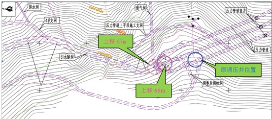
The upstream surge chamber is 90.5 m high with a lined internal diameter of 30 m. Following the start of construction, and based on geological conditions revealed during excavation of the surge shaft access/inspection adit, updated geological forecasts, and expert recommendations from the feasibility study phase, the design team conducted a dedicated optimization study on the type and location of the upstream surge chamber from June 2022 to June 2023.Throughout this process, multiple consultation sessions were held with leading industry experts. The final selected方案 was to relocate the cylindrical surge chamber 87 m upstream, where the geological conditions proved significantly more favorable. This optimized layout enabled remarkably efficient excavation:
- Dome excavation completed in just 1.5 months
- Shaft excavation completed in 4 months
During excavation, the design team further carried out real-time optimization of excavation and support measures based on actual ground conditions. A key innovation was the replacement of conventional prestressed anchor cables with long rock-socketed micropiles (anchor piles) in the middle-to-lower section of the shaft. This alternative support scheme was verified as technically feasible and offered multiple advantages:
- Estimated investment savings: approximately RMB 2.34 million
- Elimination of complex post-tensioning operations, simplifying construction
- Significantly reduced construction difficulty
- Schedule acceleration by about 3–4 months
This series of optimizations exemplifies a responsive, geology-driven design approach that enhanced safety, economy, and constructability for one of the project’s most critical underground structures.
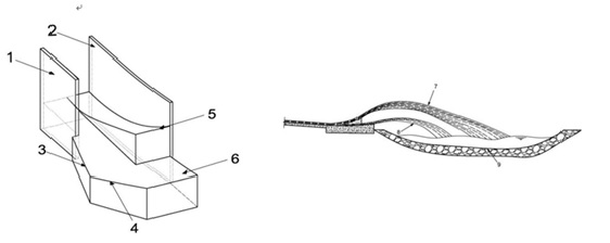
3.5 Dual-surface differential flip bucket
In mountainous rivers characterized by narrow valleys, steep bed slopes, and high discharge volumes, hydraulic and hydropower projects commonly adopt ski-jump (flip bucket) energy dissipation. However, this method often suffers from inadequate energy dissipation, leading to severe downstream scour.
To address this issue, during the early construction phase, a hydraulic model testing and optimization study was jointly conducted with Sichuan University. The research recommended the adoption of a dual-surface differential flip bucket. This innovative design splits the jet flow into two distinct upper and lower streams, creating two vertically separated water tongues. As a result, the discharged flow achieves enhanced three-dimensional diffusion and dispersion in the air and upon impact.
This configuration effectively:
- Reduces the depth of the downstream scour pit, and
- Confines the impingement zone of the water jets, preventing erosion of adjacent valley slopes and nearby structures.
The dual-surface differential flip bucket thus provides a robust solution for safe and efficient energy dissipation in high-head, high-discharge alpine hydropower projects.
Dual-fan differential flip bucket
四、Summary
As one of the final projects in the State Grid’s 2025 Peak Summer Power Supply Assurance Initiative, the Balа Hydropower Station has a designed annual average electricity generation of 2.553 billion kWh, sufficient to meet the basic annual production and living electricity needs of approximately 1 million households.
This output is equivalent to:
- Saving about 1.16 million tons of standard coal per year, and
- Reducing CO₂ emissions by approximately 3 million tons annually.
The commissioning of the station will significantly enhance Sichuan power grid’s peak summer supply capacity and improve regional power supply reliability.