
Selection of Main Electrical Wiring for Bala Power Station
Abstract: This article provides a detailed introduction to the selection of the main electrical connection scheme for the Bala Hydropower Station in Aba Tibetan and Qiang Autonomous Prefecture, Sichuan Province. It compares the combination methods of generators and transformers, as well as the connection methods on the 500kV side, offering reference for the design of similar hydropower projects.
Keywords: Hydropower Station, Main Electrical Connection, 500kV
1. 1、Overview
The Bala Hydropower Station is located in Ribu Township, Barkam County, Aba Tibetan and Qiang Autonomous Prefecture, Sichuan Province. It is the second cascade hydropower station in the Jiaomuzhu River section of the Dadu River mainstream hydropower planning “3 Reservoirs, 22 Levels”. It is connected to the “dragon head” reservoir hydropower station of Xiaerge above and the Dawei cascade hydropower station below. The power station adopts a mixed development method with daily regulation capability. The installed capacity of the power station is 720MW, with an average annual power generation of 2.584/3.027/2.495 billion kW·h (separate/joint/considering joint water transfer). The development task is hydropower generation and ecological water use. After completion, the power station will supply power to the Sichuan power grid.
The main structures of this project include a concrete-faced rockfill dam, spillway tunnel, flood discharge and diversion tunnel, and power generation system. The project is located in a high mountain gorge with complex terrain. The underground powerhouse system is located in the granite mountains on the right bank and is arranged in parallel with three rows of main powerhouse, auxiliary powerhouse, and main transformer cave.
2. 2、 Power Station Access System Scheme
According to the design report of the power station access system scheme, the access system scheme for Bala Hydropower Station is as follows: The outgoing voltage level of Bala Hydropower Station is 500kV, with two outgoing lines: one connected to the Aba UHV substation and the other connected to Xiaerge Hydropower Station. Through the Xiaerge-Dawei-Busi communication channel, it is connected to the Aba UHV substation. In addition, to coordinate the power transmission of Bala ecological units, Mulang River, and Murjia Gou, Bala Hydropower Station needs to reserve one 110kV/500kV interconnection step-up transformer position for its access.
The design work of the power station in this stage will be carried out based on this access system scheme.
3. 3、Selection of Main Electrical Connection
3.1 Selection of Generator and Transformer Combination Methods
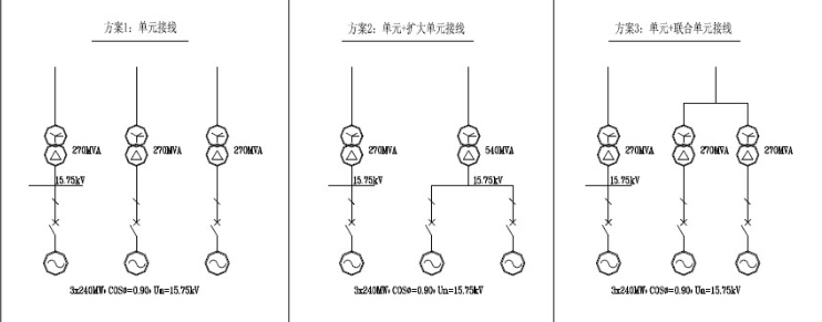
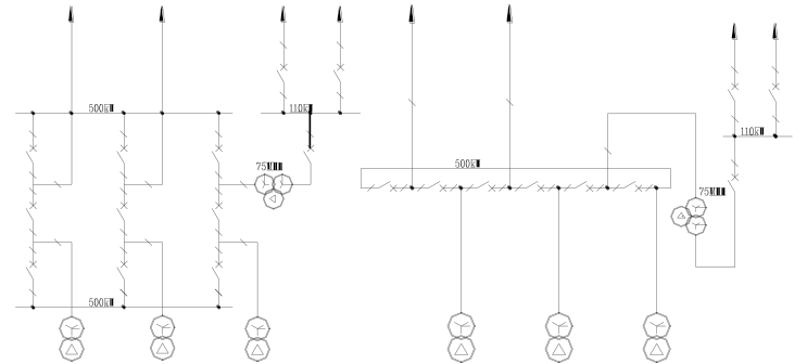
Bala Hydropower Station has three units, each with a capacity of 240MW. The initial proposed scheme for generator-transformer combination is as follows (simplified connection diagram see Figure 1):
Scheme 1: Unit connection, with three main transformers of 270MVA capacity each;
Scheme 2: Unit + expanded unit connection, with two main transformers of 270MVA and 540MVA respectively;
Scheme 3: Unit + combined unit connection, with three main transformers of 270MVA each.
To improve the safety, reliability, and flexibility of the power station operation, generator circuit breakers are installed at the generator outlet in all the above schemes.
(1) Reliability Comparison
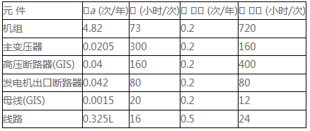
Based on the original reliability parameters of each electrical component of the main electrical connection collected so far (see Table 1), it can be known that the failure rate of the 500kV transmission line is much higher than that of other major electrical components. Therefore, even if the generator-main transformer combination adopts the unit connection method with higher power supply reliability, the reliability index of the power station wiring is mainly restricted by the line reliability, and the reliability index difference of the above three generator-main transformer combination schemes is not significant.
Table 1: Original Reliability Parameters of Main Electrical Connection Components
(2) Economic Comparison
Unit connection and combined unit connection have basically the same investment on the generator voltage side. Expanded unit connection reduces the number of main transformers from three to two, saving equipment investment, but the single-phase nitrogen-filled transport weight of the expanded unit main transformer exceeds 110t. According to the heavy haulage conditions of the power station, the existing conditions are difficult to meet, and the transport cost will increase due to the need for reinforcement of the bridges along the route.
(3) Technical Comparison
1)Short-Circuit Current Calculation and Generator Voltage Equipment Parameter Selection
For the short-circuit current on the generator voltage side, the combined unit connection and unit connection are the same. When the generator subtransient reactance (Xd") is 0.20, the impedance voltage (Uz%) of the main transformer is 0.14, and the generator voltage is 15.75kV, the short-circuit current calculation results on the generator voltage busbar of the unit connection and expanded unit connection are as follows:
Table 2: Short-Circuit Current Calculation Results for Generator Terminal of Expanded Unit Connection and Unit Connection
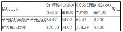
From the above table, it can be seen that the short-circuit capacity on the generator voltage side of the expanded unit connection is much larger than that of the unit or combined unit connection. When the generator circuit breaker trips at 0.06s, the short-circuit current period component is slightly greater than 160kA. After communicating with manufacturers such as Alstom and ABB, it is found that it exceeds the short-circuit breaking capacity of the existing conventional generator circuit breakers, causing difficulties in selecting the generator circuit breaker and increasing equipment investment.
2)Main Transformer Selection and Heavy Haulage
The capacity of the expanded unit main transformer is 540MVA, and the transport weight of both the combined three-phase transformer and the single-phase transformer exceeds 110t; for the unit connection or combined unit connection method, the capacity of the main transformer is 270MVA, and the transport weight is about 90t when using the combined three-phase transformer or single-phase transformer.
The heavy haulage of Bala Hydropower Station is carried out by road transport. The route is from Chengdu along National Highway G317 through Dujiangyan, Wenchuan, and Barkam to Rejiao, and then along the river highway from Rejiao to Xiaerge Hydropower Station to the construction site. The section of G317 from Dujiangyan to Wenchuan is 75km long, with a secondary road and bridge design load of automobile-20 and trailer-100; the other sections basically meet the standards of Class III mountainous and hilly area roads, with a subgrade width of 7.5m, a pavement width of 6.0m, asphalt pavement, and some bridges with a design load of automobile-15 and tractor-80.
1)The transport weight of the conventional three-phase transformer is large, about 200t for the 270MVA three-phase transformer, which is difficult to meet the transport requirements, so none of the three schemes recommend using it.
2)Combined three-phase transformer or single-phase transformer group type:
Unit or combined unit: partial bridge load reinforcement is required, which can basically meet the heavy haulage requirements of the power station; expanded unit still difficult to meet the heavy haulage conditions;
3)Comprehensive Comparison
The unit connection scheme has one more main transformer incoming line interval than the combined unit connection, with slightly higher investment in 500kV distribution equipment, but it has the advantages of clear and concise wiring, small fault impact range, reliable and flexible operation, convenient equipment layout, and simple relay protection; the capacity of the main transformer in this connection scheme is 270MVA, and if single-phase or combined three-phase transformers are used, the transport weight is less than 100t, meeting the weight limit requirements of the power station’s road transport.
Compared with the unit connection, the combined unit connection reduces the electrical equipment on the high-voltage side of the main transformer, resulting in lower equipment investment; but there is a tie bus and disconnector on the high-voltage side of the main transformer, making the wiring more complex, and as this power station is an underground powerhouse, the layout site for the high-voltage side of the transformer is limited, making the layout difficult; the operation and running flexibility of the combined unit connection is poorer than that of the unit connection, and if one of the main transformers in the combined unit fails or is under maintenance, both units connected to the combined unit need to be shut down temporarily, and after the disconnector switching operation, the other unit can continue to operate. The transport weight of the main transformer in this connection scheme is the same as that of the unit connection.
The expanded unit connection scheme reduces the number of main transformers and investment and is beneficial for equipment layout, but when the expanded unit main transformer or generator voltage equipment is under maintenance or failure, it will affect the power transmission of two units of the power station; the short-circuit capacity on the generator side is too large, exceeding the breaking level of conventional generator circuit breakers, which causes difficulties in the next stage of equipment bidding; and the main transformer capacity is large, and the single-phase nitrogen-filled transport weight is difficult to meet the heavy haulage requirements of the power station, with significant costs for bridge reinforcement and modification along the route.
Bala Hydropower Station is a daily regulation power station. When operated in conjunction with the upstream “dragon head” reservoir hydropower station of Xiaerge, it can make the entire Jiaomuzhu River cascade hydropower stations reach the capacity of seasonal regulation and above, undertaking a certain peak regulation task in the system. Therefore, considering the reliability and operational flexibility of the main electrical connection, and the ability to adapt to the frequent start-stop operation of the units, the generator-transformer combination method recommended in this stage is Scheme 1, that is, three Francis turbine generators are connected to three main transformers respectively to form a unit connection scheme.
3.2 Selection of 500kV Side Connection Scheme
3.2.1 Proposed 500kV Side Connection Scheme
According to the power station access system data and generator-transformer combination method, the generator-transformer set of this power station adopts a unit connection type, with 6 incoming and outgoing lines (including tie transformer incoming line) on the 500kV side, which can be connected in double busbar connection, 3/2 circuit breaker connection, and delta connection.
Since this power station has only one outgoing line to the Aba UHV substation, and the reliability of the transmission line is much lower than that of other major electrical components (see Table 1 “Original Reliability Parameters of Main Electrical Connection Components”), the reliability of the main electrical connection will mainly depend on the failure rate of the transmission line. From this perspective, both double busbar connection, 3/2 circuit breaker connection, and delta connection are feasible for this power station and can be used as alternative schemes for the main electrical connection.
Therefore, the following three main electrical connection schemes are proposed for comparison.
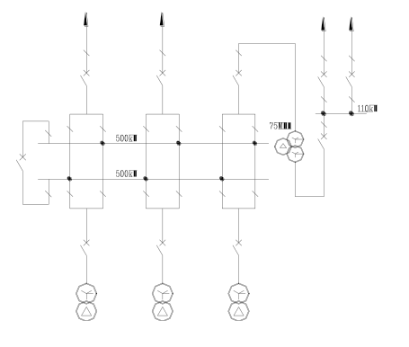
Scheme 1: Generator-transformer unit connection, 500kV side double busbar connection;
Scheme 2: Generator-transformer unit connection, 500kV side 3-string 3/2 circuit breaker connection;
Scheme 3: Generator-transformer unit connection, 500kV side hexagonal connection.
(2) Technical Comparison of Each Connection Scheme
The advantages and disadvantages of the three connection schemes are compared in Table 3.
Table 3: Technical Comparison of 500kV Side Connection Schemes
Scheme | Scheme 1 (Double Busbar Connection) | Scheme 2 (3/2 Circuit Breaker Connection) | Scheme 3 (Hexagonal Connection)
1. High power supply reliability, each circuit has two circuit breakers | 1. Simple and clear wiring, simple relay protection, convenient operation and maintenance | 1. 500kV side 6 sets of circuit breakers form a closed loop, no busbar
2. Maintenance of any busbar group will not cause power interruption | 2. Flexible operation and dispatching, two busbar groups and all circuit breakers are in operation in normal operation, forming a multi-loop power supply mode | 2. Each incoming/outgoing circuit connects two circuit breakers, any circuit breaker maintenance does not affect the continuous power supply of the circuit
3. Maintenance of any circuit busbar disconnector only affects the power supply of that circuit | 3. Busbar maintenance does not need to switch the secondary circuit | 3. 500kV distribution equipment is less, investment is relatively low
4. Good adaptability to system changes | 4. Simple busbar maintenance, no need to switch the secondary circuit during busbar maintenance | 4. Poor adaptability to system changes
From the technical comparison in the above table, it can be seen:
· The double busbar connection and delta connection both form open-loop operation, and any circuit breaker failure will cause a short-term power failure of the entire plant, reducing the operational reliability;
· In the 3/2 circuit breaker connection, each string of 3 circuit breakers corresponds to 2 incoming and outgoing circuits. When one circuit breaker is opened, power supply can still be maintained; from the qualitative analysis of connection reliability, the 3/2 circuit breaker connection method is slightly better in reliability and safety than the double busbar connection and delta connection schemes. However, since this power station has two 500kV outgoing lines, considering that the failure rate of the transmission line is much higher than the failure rate of the 500kV equipment in the power station, the power supply reliability of the power station will mainly be restricted by the reliability of the transmission line, so the reliability advantage of the 3/2 circuit breaker connection cannot be fully reflected.
· In terms of investment, the number of circuit breakers in the double busbar connection and delta connection is 7 and 6 respectively, which is less than the 9 in the 3/2 circuit breaker, with lower investment and better economy.
· In terms of relay protection configuration, the double busbar connection is slightly simpler.
· This power station has 4 incoming and 2 outgoing lines, the more incoming/outgoing lines, the less suitable for using delta connection. Generally, no more than 6 delta connections are used in domestic power stations when using ring connection.
· From the perspective of long-term planning, the double busbar connection is more adaptable to system changes than the other two schemes.
(3) Economic Comparison of Each Connection Scheme
This power station is an underground powerhouse layout, and the 500kV switchgear station is arranged on the ground. If conventional medium-sized equipment layout is adopted, the ground switchgear station area will be about 250x150m, and the required civil engineering excavation slope height will reach 330m. In order to save equipment layout space, reduce civil engineering excavation and lower the slope height, it is recommended to use GIS distribution equipment for the 500kV switchgear station. Based on this premise, the economic comparison of each main electrical connection scheme is shown in Table 4.
Table 4: Economic Comparison of Main Electrical Connection Schemes (Unit: 10,000 yuan)
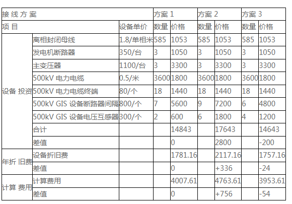
Note: a) The annual depreciation expense in the table is calculated using a depreciation maintenance rate of 12%; b) The calculation formula for the calculation expense is J = F + Xb·Z. Where: J is the calculation expense; F is the annual depreciation and maintenance cost; Z is the equipment investment; Xb is the economic effect coefficient, which is 0.15.
From the analysis of the above table, it can be seen that compared with the double busbar connection and delta connection, the investment and calculation cost of the 3/2 circuit breaker connection scheme increase significantly, with poor economy.
3.2.2 Final 500kV Side Connection Scheme
Based on the above technical and economic comparison of the 500kV side connection of Bala Hydropower Station, it can be seen that the double busbar connection has the advantages of simple and clear wiring, simple relay protection, convenient operation and maintenance, and the best adaptability to system changes in the long-term planning. Although the reliability analysis of the main connection shows that the 3/2 connection is slightly better than the double busbar connection and delta connection, due to the two outgoing lines of this power station, the reliability
The provided text is a detailed technical document discussing the selection of the main electrical connection scheme for the Bala Hydropower Station in Sichuan Province, China. The document outlines various aspects such as the generator-transformer combination methods, the 500kV side connection options, reliability, economic comparisons, and technical evaluations.
Here’s a summary of the key points:
1. Location and Overview:
o The Bala Hydropower Station is located in Ribu Township, Barkam County, Aba Tibetan and Qiang Autonomous Prefecture, Sichuan Province.
o It is part of the Dadu River mainstream hydropower planning and has an installed capacity of 720MW.
2. Access System Scheme:
o The station will be connected to the grid through two 500kV outgoing lines: one to the Aba UHV substation and another to Xiaerge Hydropower Station.
o An additional 110kV/500kV interconnection step-up transformer position is reserved for future power transmission needs.
3. Generator-Transformer Combination Methods:
o Three schemes are proposed for the generator-transformer combination: unit connection, unit + expanded unit connection, and unit + combined unit connection.
o Each scheme is evaluated based on reliability, economic factors, and technical feasibility.
4. 500kV Side Connection Schemes:
o Three options are considered for the 500kV side: double busbar connection, 3/2 circuit breaker connection, and hexagonal connection.
o Each option is compared in terms of technical simplicity, reliability, flexibility, and economic investment.
5. Reliability and Economic Comparisons:
o The reliability of each scheme is assessed, taking into account the failure rates of various electrical components.
o Economic comparisons are made based on equipment costs, maintenance, and operational expenses.
6. Final Recommendations:
o Based on the comprehensive analysis, the unit connection method is recommended for the generator-transformer combination due to its simplicity, reliability, and flexibility.
o For the 500kV side, the double busbar connection is chosen due to its simplicity, cost-effectiveness, and adaptability to future system changes.
The document concludes by emphasizing the importance of selecting a suitable electrical main connection scheme for ensuring the safety, efficiency, and economic viability of hydropower projects. It also notes that while the 3/2 circuit breaker connection offers higher reliability, the additional investment and complexity do not justify its use in this specific case, given the two outgoing lines and the constraints imposed by the transmission line reliability.