
Selection of electrical main wiring for SC power station
Abstract
This article mainly analyzes the selection of the main electrical connection and the form of the main electrical equipment for the Santa Cruz Hydropower Station in the Republic of Ecuador. Through comprehensive technical and economic comparisons, a preliminary electrical main connection method that meets the operation reliability of the power station and the requirements of the Ecuadorian power grid has been determined.
Provide Abstract & Keywords only, not the full-text
Keywords: Ecuador, Technical Comparison, Economic Comparison
1. Power Station Overview
The Santa Cruz Hydropower Station (hereinafter referred to as SC Hydropower Station) is located on the right bank of the Machinatza River, a first-class tributary of the Zamora River in the southeastern part of Zamora, Zamora-Chinchipe Province, Republic of Ecuador. It is a non-regulated diversion type hydropower station.
The SC Hydropower Station is a captive power plant for the Mirador Copper Mine and is capable of supplying power to the grid. The development task of the power station is hydropower generation, taking into account the water supply for the downstream ecological environment. The power station does not perform system peak shaving or frequency regulation tasks. If necessary, the reservoir can be lowered to a water level of 1180.0m or 1178.0m to meet the peak shaving requirements for about 0.5 hours.
The SC Hydropower Station adopts a layout plan with a downstream powerhouse, a left-bank diversion line, and a left-bank ground powerhouse. The power station uses a diversion development method with a diversion tunnel about 4.7km long. The power station is equipped with 3 mixed-flow units with a total installed capacity of 129MW, an average annual generation of 766.2 million kW·h, an annual utilization hour of 5939h, and a guaranteed output of 29.3MW.
2. Power Station Connection to the Power System
The SC Hydropower Station is a captive power plant for the Mirador Copper Mine. The power station is equipped with 3 hydro-turbine generating units, each with a capacity of 43MW, for a total installed capacity of 3×43MW.
According to the preliminary power station connection system information provided by the owner, the power station connection system plan at this stage is tentatively determined as follows: The high-voltage side of the power station adopts a 230kV level, and one outgoing line is connected to the central substation of the Mirador mining area, with a line length of about 11km.
3. Electrical Main Connection
3.1 Electrical Main Connection Scheme
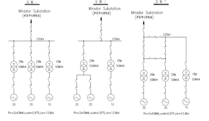
With an installed capacity of 3×43MW and the power station connection system scheme, and based on the comprehensive analysis of kinetic characteristics parameters, the connection between the generator and the transformer is preliminarily proposed with the following three schemes for technical and economic comparison:
Scheme 1: Three hydro-turbine generating units are connected to three main transformers to form three unit connections, each with a main transformer capacity of 50MVA, 230kV high-voltage side equipment with three incoming lines and one outgoing line, using a single-busbar connection method.
Scheme 2: One hydro-turbine generating unit is connected to one main transformer to form a unit connection, with a main transformer capacity of 50MVA, and the other two hydro-turbine generating units are connected to one main transformer to form an extended unit connection, with a main transformer capacity of 100MVA; 230kV high-voltage side equipment with two incoming lines and one outgoing line, using a single-busbar connection method.
Scheme 3: Three hydro-turbine generating units are connected to three main transformers to form three unit connections, each with a main transformer capacity of 50MVA, 230kV high-voltage side equipment with three incoming lines and one outgoing line, using a quadrilateral connection method.
3.2 Technical Comparison of Connection Schemes
(1) Technical Comparison of Generator Voltage Side Connection Schemes:
1)Unit Connection Scheme:
(a) Symmetrical connection, clear and concise, simple relay protection, flexible operation, and small impact range of failure or maintenance.
(b) Flexible and convenient unit operation, with one outgoing line from the 1# and 3# generating units for station service power supply; easy selection of high-voltage circuit breakers for station service branch circuits;
(c) Unit connection main transformer capacity of 50MVA, using a three-phase transformer, with a nitrogen-filled transportation weight of about 60t, which is beneficial for meeting the power station’s road transportation requirements.
(d) The number of main transformers and the high-voltage incoming line intervals are more than the extended unit connection scheme, increasing the layout site and 230kV equipment investment.
2)Extended Unit Connection Scheme:
(a) Due to the long distance from the power station to the grid hub substation (about 135km), the estimated short-circuit current period component of the extended unit generator outlet is less than 50kA, and the generator voltage equipment is selected as conventional equipment.
(b) The short-circuit current of the extended unit station service branch circuit is larger than that of the unit connection, and the circuit breaker investment is more expensive;
(c) Compared with the unit connection scheme, there is one less 230kV side incoming line interval, and the 230kV equipment investment is less;
(d) Once the extended unit main transformer fails or is under maintenance, it will cause two-thirds of the power station’s power output to be blocked;
(e) The extended unit connection main transformer capacity is 100MVA. If a three-phase transformer is used, the nitrogen-filled transportation weight is heavier (about more than 80t), which is difficult to meet the power station’s road transportation requirements; if a three-phase combined transformer is selected, it is easy to meet the power station’s road transportation restriction requirements, but the on-site electrical and mechanical connection work is more complicated, and the main transformer equipment investment is larger.
3)Scheme Selection:
According to the above comparison, the reliability and flexibility of the extended unit connection are slightly worse than those of the unit connection. Although the comprehensive investment of the unit connection is slightly higher than that of the extended unit connection, considering that the transportation weight of the extended unit main transformer is large and the on-site transportation conditions are difficult to meet, while the unit connection method is more flexible and can meet the reliability of mine power supply and large equipment transportation requirements. Considering the operation reliability, flexibility, power station road transportation conditions, and station service power supply reliability of the power station’s electrical main connection, it is recommended that the unit connection is more suitable for the generator-transformer side connection.
(2) Technical Comparison of 230kV High-Voltage Side Connection Methods:
1)Single-Busbar Connection Scheme: The main advantages of the single-busbar connection method are simple connection, reliable power supply, flexible operation, and simple relay protection, with only one set of P.T interval on the 230kV side. The disadvantage is that a busbar failure will cause a complete plant power failure. Considering the use of SF6 fully enclosed combined electrical (GIS) equipment, the failure rate is extremely low, and its reliability can fully meet the operation requirements of the power station.
2)Quadrilateral Connection Scheme: The main advantages of the quadrilateral connection are high power supply reliability, convenient and flexible operation, and no impact on the continuous power supply of the power station when any circuit breaker on the 230kV side is under maintenance. The disadvantages are relatively complex secondary protection and layout, and when any circuit breaker is under maintenance, it operates in an open loop, thereby reducing the connection reliability, and there is one more set of P.T interval than the single-busbar connection.
3.3 Economic Comparison
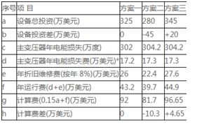
In the economic comparison of the scheme, only the differential part (230kV side electrical equipment) is compared. The power loss is calculated at 0.057 US dollars/kW·h, and the equipment depreciation and maintenance rate is 8% per year. The economic comparison of each scheme is shown in Table 1.
Table 1
3.4 Electrical Main Connection Scheme Selection
According to the economic and technical comparison of the three schemes, Scheme 3 has the highest investment, the highest annual operating cost, and the highest calculation cost; Scheme 1 has slightly higher costs than Scheme 2, but it is more flexible, convenient, and reliable in operation.
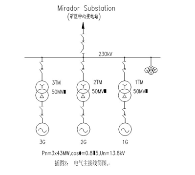
In summary, based on the technical and economic comparison of each scheme, the recommended electrical main connection scheme for this stage of the power station is: the three hydro-turbine generating units are connected to three main transformers to form three unit connections, with a main transformer capacity of 50MVA for each; the 230kV side adopts a single-busbar connection, with circuit breakers installed on the high-voltage side of the main transformer and the outgoing line, and one outgoing line is connected to the central substation of the mining area. In order to more flexibly meet the power station’s access/supply requirements, one outgoing line interval of 230kV is reserved, and the outgoing line circuit is not ordered at this stage. In the next stage, the electrical main connection scheme will be further optimized according to the final connection system scheme of the power station and the determination of the road transportation restriction conditions.
4. Selection of 230kV High-Voltage Distribution Device Form
The 230kV high-voltage distribution device considers two different layout schemes of conventional open-type electrical equipment and SF6 fully enclosed combined electrical equipment (GIS).
GIS Layout Scheme:
The GIS room is arranged above the ground main transformer room, with the same length as the main transformer room, and a height of 11.5m; the GIS equipment is directly connected to the high-voltage side bushing of the main transformer, and the 230kV outgoing equipment is arranged on the roof of the GIS room.
Open-Type Layout Scheme:
The 230kV switchgear station is arranged on the left side of the power station (facing downstream), with dimensions of 70m×60m. The economic comparison of the two schemes is shown in the following table (the same part does not participate in the comparison):
Economic Comparison of GIS Scheme and Open-Type Scheme
Table 2
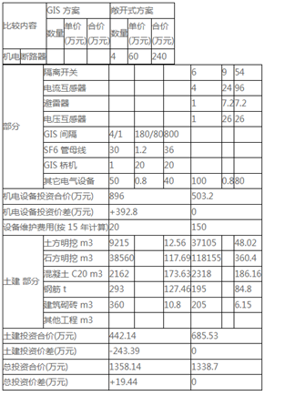
After preliminary estimation, the equipment investment of the GIS scheme is 3,928,000 yuan more than that of the open-type scheme, and the civil engineering investment is nearly 2,433,900 yuan less than that of the open-type scheme, but considering the annual operation and maintenance cost of outdoor open-type equipment, the comprehensive investment of the GIS scheme is slightly higher than that of the open-type scheme by 194,400 yuan. Comprehensive comparison, although the comprehensive investment of the GIS scheme is slightly higher, the GIS layout scheme has high seismic performance, is not affected by the environment; the layout is centralized, covers a small area, is easy to manage; and has safe operation, extremely small maintenance workload, long maintenance cycle; in terms of operational reliability, it is even more advantageous. With the improvement of technical level and the reduction of manufacturing costs at home and abroad, GIS equipment has been widely used in hydropower stations. Since the project of this power station is for self-use by the mine, the annual utilization hours are high, and the requirements for equipment operation reliability are high, the 230kV high-voltage distribution device is tentatively determined to use fully enclosed combined electrical equipment (GIS) at this stage.